I was a Radio Officer and later technical R/O on board Queen Mary (GBTT) intermittently from 1952 to 1957. The following describes the changes and the equipment used relative to the article in the "Shipbuilder" shown on Julian Hill's web site.
The Transmitting Room.
The changes here are the removal of the high power long wave transmitter and the aerial tuning units, presumably associated with the short wave transmitters 1 and 2. The long wave transmitter was replaced by a short wave 1 kW C. W/300 Watt Telephone transmitter type ES4A made by Standard Telephones and Cable, CO.
This transmitter was a six band, four frequencies per band, type. Each band consisted of manually tuned inductors arranged vertically each with its own contactor solenoid to connect the appropriate inductor to the multiplier and PA valves. The PA valve was a pentode about 18 inches high , 8" diameter, suppressor modulated in telephone use. Each of the frequencies in each band was crystal controlled. The bands were the standard marine ones of 4,6,8,12 and 16 Megacycles. The band and frequency selection was by the standard telephone technique of dialing the band and frequency required on a rotary telephone dial (Strowger Dialling.) in the radio receiving room. Incidentally, the first Queen Elizabeth used 3 of these transmitters, two for telephone use.
The Medium wave transmitter covered both the 600 to 800 metres (500 to 400 kHz) and a couple of long wave frequencies (2000 metres 143 kHz) . The transmitter was again of Standard Telephones and Cable Co. manufacture.
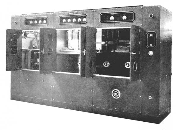
Referring to the pictures on page 2 of the article in the `Shipbuilder' (above), the left hand section contained the power supply transformer and the mercury vapour rectifier valves. Rumor had it that these valves were installed in 1936 and not been changed by 1957. The second bay held the capacitor/inductor oscillator valve and the two P.A. valves. These used to run red hot, not keyed, and cooled down when keyed. The power out being 1 1/2 kW full power but usually used at the ū kW output level, giving about 12 amps to the aerial but increased to 18 amps after a good clean in about 1958. This transmitter was modified to crystal control in about 1959.
The final bay held the P.A. and aerial tuning inductors. The switching for each frequency was by a very large vertical assembly driven by an electric motor with an extension to the oscillator section in the second bay. The whole assembly changed the tapping points on the various tuning coils.
This transmitter had both continuous wave and modulated continuous wave capability. The motor alternator shown on the transmitting room layout gave about 750 watts at 1000 cycles (Hz) for MCW use with the medium wave transmitter. The motor alternator was started and controlled from the power board. Again, frequency selection of the transmitter was by telephone dialling.
The short-wave long range transmitters shown on the transmitter room layout were used exclusively for telephone traffic in the 4,8,12, 16 MHz bands. I believe they were made by RCA although I am not certain on that point. Again, the frequency was selected by telephone dialing the channel required; there being one frequency per channel. On dialing a frequency a large bellcrank and levers operated the connections of the manually tuned inductors to the valve circuits, again arranged in vertical rows. I suspect there were 6 channels on this equipment and not the 10 mentioned in the Shipbuilder write up. I do remember it was necessary to change two crystals in each transmitter when in New York and Southampton, to cater for different frequencies used when Westbound, compared with Eastbound.
The oscillator was crystal controlled. A Pierce crystal oscillator running at (I think) about 5 watts drove multiplier valves The penultimate stage was anode modulated which in turn drove the class B. P.A. stage at about 300 watts output. One transmitter held the frequencies for calls to America, the other frequencies for use with the British Post Office.
The final piece of equipment in the transmitting room was the Power board. Apart from controlling the Medium wave transmitter modulating alternator, the Power board contained the starting and frequency control equipment (Brown Boveri) of the DC to AC converter motor alternators, changing the ship`s supply of 220 volt DC to 240 volts 50 cycles AC for all the radio equipment in the transmitting and receiving rooms, and some of the bridge gear, radars and short range radio telephone etc. The motor alternators themselves were situated down in cabin class area in a small room on either C, D or E deck. Sorry, can't remember which.
I don't know how the original aerials were fitted. However, in `52 and onwards the medium wave aerial ran via copper tubing on 6" standoff insulators to the deck feed through insulator and then to twin L aerials from the mainmast top yard and number 3 funnel. The short wave (H. F) aerials again ran in copper tubing to the deck feed through insulators and then to individual vertical aerials supported from a jack stay from the mainmast to number 3 funnel.
The Receiving Room
The main changes here were that the telegraph office was entered from the clerical office. The entrance telegraph office/radio room was blocked off. The door between the radio room and the battery room was also blocked off. By the way, the battery room held emergency supplies for the bridge and possibly passenger areas and had nothing to do with the radio equipment. The ventilator shown on the receiving room plan was against the after bulkhead near the power control board. It was fitted with footholds and provided an escape route if required, and access to the receiving aerials.
Additional lighting was also fitted, consisting of a row of neon tubes on the ceiling running at about 15 Kilovolts; these were fed from the radio A. C supply. There were a few changes to the operating positions.
Position # 1 . Medium wave (500Kz) distress watch, ship and medium wave shore station communications and long wave communications which was rarely used. I think only once in my time aboard.
Position # 2. Short wave telegraph traffic and reception of daily news reports for the ship's newspaper.
Position # 3 Telephone traffic to America via WOO station (Ocean Gate)
Position # 4 Telephone traffic to United Kingdom Via Rugby (Transmit) and Ongar (Receive)
The emergency gear was a standard emergency transmitter as fitted to most deep sea ships. running off 24Volt batteries situated on the deck above the radio room.
There were a few equipment changes in the radio room.
The Position # 4 (U.K.Phone) receiver was changed to a Hammarlund SP600 JX and Position # 3 (America Phone) changed to another Hammarlund receiver Type unknown. It looked like an earlier version of the SP600 type. Position #2 was changed to an Eddystone receiver used as the main receiver; a buff coloured receiver of S.T.C manufacture was used as a standby. This receiver is apparently still on board in the Amateur Operators club suite. It is shown in the web site photo-the first receiver visible on the left hand side of the photo. (The one with the semicircular dial.)
Position #1 (medium/long wave communications) used T. R. F. receivers, probably from the initial installation. These worked well.
All receivers were fed via coaxial cables from vertical aerials fitted from a jack stay between no 1 and 2 funnels. The switching and equipment at the top of the operating bays shown in the Shipbuilder Photographs had been removed in my time and was probably associated with aerial switching to the receivers. The transmitters were controlled from panels containing telephone dials and switches fitted at the bottom of each bay of equipment. Additional panels were fitted to the telephone positions to enable the operator to talk to shore and the ship's telephone exchange or passenger. Each position was fitted with a typewriter placed in a well, and of course a Morse key and headphone sockets. The telephone positions also had sockets for carbon microphones. Another change was the fitting of a Grounding tape recorder close to the emergency transmitter to record the BBC overseas news in place of a wire recorder which apparently would regularly break down spewing yards of wire onto the deck.
Only one tape punch was fitted in my time and that was never used. The supervisor's desk seemed to be as fitted at installation, allowing any audio signal to be patched to any position (or monitored). Operationally, we had very similar problems to those encountered by Ken Mugridge. Medium wave and short wave telegraph work was by Morse code and straightforward and pretty routine. The biggest chore was the nightly press reception, a solid 2 to 3 hour session of receiving the day's news and stock market reports, which used to start at about 25 words a minute and gradually wind up to 30 or more words a minute if there was a lot of news. This was not difficult when radio conditions were good but hard during magnetic storms which gave poor reception, especially on the North Atlantic run.
As Ken Mugridge says, radio telephone traffic was hard. This was partly due to the age and type of equipment used which was amplitude modulated, very similar to ordinary medium wave household broadcast systems e.g. BBC etc Unfortunately, every time the ship rolled or vibrated the contacts in the telephone transmitter and/or any other transmitter in use and some of the stays on the ship's rigging would produce a tiny spark. resulting in an atmospheric crackle in the received telephone call. Modern ships have a system known as single sideband where the transmitted carrier is much reduced to about 30 watts compared with the 300 watts used with amplitude modulation systems, eliminating most of the atmospheric problem.
Another problem was trying to make phone calls to the UK The technical operator sounded fine, the traffic operator was lower in level, but by the time the person called was on they were down in the noise. I never found out why. What was interesting was the increase in telephone calls if you managed to set up a good circuit? When that happened passengers would be queuing up to talk to all and sundry!
In general all the equipment worked well. More trouble was experienced after a refit and "maintenance" when sticking contacts etc caused trouble for a trip or two until everything settled down to working again, hammering home the old adage `if it is not broke don't fix it `
Other equipment.
A 68-pair telephone cable ran from the receiving room to the transmitting room, routed from Sun deck down to Main deck along main deck and then up to the transmitting room.
The bridge equipment looked after by the radio staff were the D. F receiver, the short range (1.6 to 3 MHz band) telephone transmitter used when approaching port and docking maneuvers and the radars. I think one was of B. T. H. manufacture and came as a fully fitted cabin placed just aft of the bridge with the display in the bridge This caused no trouble apart from going off lock occasionally when run for long periods. Another radar was also fitted which frankly did not work There was no relation between the aerial rotation and the displayed picture Unfortunately the fault was at the aerial end on the top of a 20 foot pole A major job to repair!
General and Staff.
In my day, I think there were 8 or 9 R/O`s compared with the 11 to 13 pre war and just after. The Chief, (forgot his name) 1st R/O Parsons, and two or three senior R/O`s who shuttled between Queen Elizabeth and Queen Mary,. Mickey Doyle, D. C. Brown and another whose name I cannot remember, Mac ?, the accounts R/O who did all the telegram acceptance etc down in first and cabin class, the technical R/O and two or three juniors. There were two R/O`s per watch. One was on 500 kHz and the other handled the H. F traffic including telephone calls. What was very noticeable was the decrease in traffic year on year as air travel took over from sea travel. By 1957 winters became very slack. with no-one in Sundeck cabins at all and a very depleted First Class passenger list. Tourist Class was usually full.
Catering arrangements were a little different from Ken Mugridge's time. The Chief and 1st R/O dined in First Class, the others in Cabin Class. I can't remember being tucked away, but rather furthest from the kitchen. What does stick was it was always Ravioli in Tuesdays and Chicken on Sundays with no menu changes trip after trip. Changes in the stewards and waiters did not seem often as far as I can remember.
When in port everyone ate First Class. Oxtail was a favoured dish. Socially, things were a bit quiet, though one event is remembered. The telephone operators at WOO (Ocean Gate) were invited down to a party. Since they were on shift work like us the party lasted for about 3 days. I missed it, being shipped off on a Star boat down to the Argentine for some months. It was still being talked about when I got back.
There were the odd tales going around, such as that during the war so many guns were put on the top decks that she went along with a 45 degree heel for some minutes, some guns being promptly unloaded at the next port of call. Carrying Royalty caused worries. Apparently during one royal trip H. M was on the phone, and the main aerial fell down for the first and only time.
Odds and Ends
Concerning putting the Radio Room back to original state. It might be possible to run the receivers off the standard US Mains frequency of 110 Volts 60 cycles by altering the taps on the mains power transformers. The IMR54 receiver shown on the club photo (the large one with the white knobs) is a "universal" type set covering 110, possibly 220, Volts D.C. and A.C. Voltages as well This was fitted after my time. However, be warned: Components used in these sets probably have changed value especially electrolytic condensers, which would need reforming if lucky, or more likely replacing. If this is not done, they are likely to explode.
As far as transmitters are concerned getting one would be nearly a miracle! I think the best you could do there would be a static display, since power voltages of 2000 Volts on around 50 year old equipment is not a good idea. As far as the emergency gear is concerned it may be possible to run this into a dummy load (500pf about 20 KVA in series with 2.5 ohms) but battery maintenance is an ongoing thankless task, also comments on the receivers apply.
I would be very interested to know how many operators were on board in Ken Mugridge's time and also whether the radio receiving room was modified compared with that described above? I know Peter Mainwaring, Depot Manager Southampton was talking about a complete revamp of the receiving room. Did it happen?