Lifeboats and other Life-saving DevicesAccording to the Shipbuilder and Marine Engine-Builder: "The lifeboats which have been placed on board the Queen Mary are all motor-driven, and, indeed, are the largest motor lifeboats yet built to be carried in davits. The contract for the whole equipment was entrusted to Messrs. Hugh McLean and Sons, Ltd., of Govan, Glasgow, and the constitution of the equipment is given in the accompanying table.
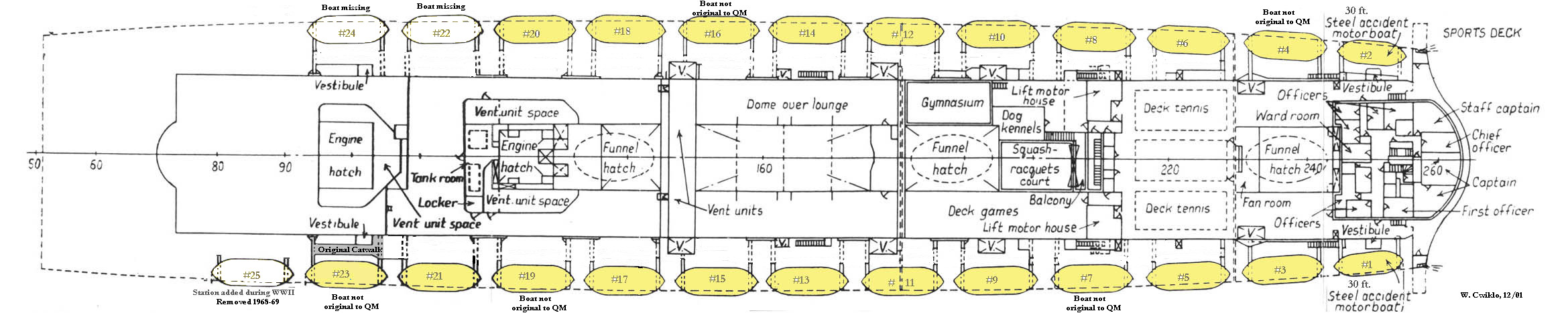
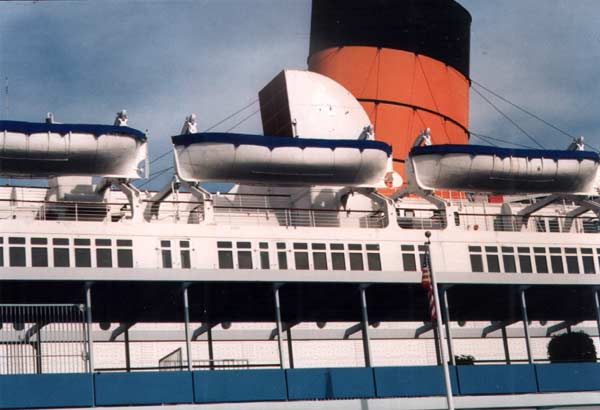
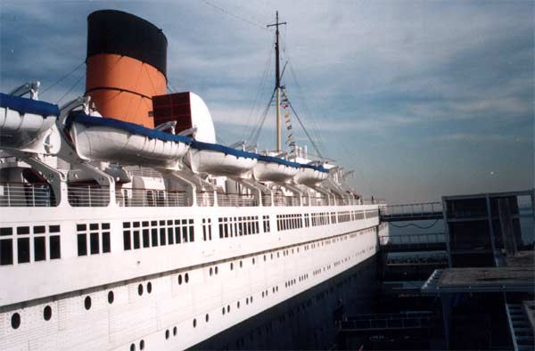
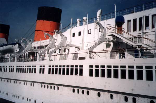
Above - the general arrangement of lifeboats on the Queen Mary
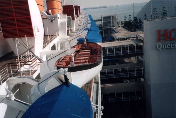
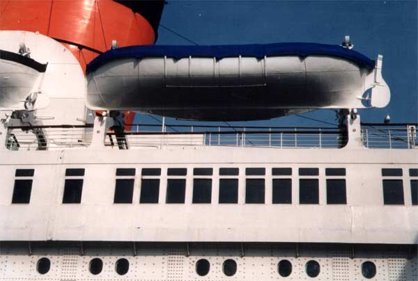
All the lifeboats are constructed of steel and it may be stated here that the approval of the Board of Trade was granted only after the boats had been shown to fulfil very stringent conditions covering strength, flotation, stability, flooding, speed and seating arrangements. Heavy steel skids are riveted to the sides and these, while adding greatly to the strength of the boats, will enable them to negotiate obstructions, such as plate edges, with safety should it be necessary to launch the boats over an expanse of shell plating, consequent upon the development of a list. The question of their form was specially considered to ensure a high standard of seaworthiness in the fully-laden condition, and to secure a satisfactory trim with adequate propeller immersion and maneuverability in the light condition. The trials clearly demonstrated that the boats possessed these qualities to a remarkably high degree. As already mentioned, the material of construction is steel; and, to reduce the risk of damage by fire, the amount of woodwork in them has been minimized. In each of the motor lifeboats two one-gallon marine-type extinguishers of the Phomene type, supplied by the Pyrene Co.. Ltd., of Brentford, Middlesex, are provided. These extinguishers are fitted with double sealing valves, which should render accidental release of the contents impossible. The capacity and arrangement of the copper buoyancy tanks, it is stated, will make these boats unsinkable, and special attention has been paid to their accessibility for inspection- no nails or screws need be removed to permit examination. The whole of the seating accommodation is disposed transversely. The side deck at the gunwale, which is l8in. wide, gives an ease of access along the boat, and has the further advantage of keeping the occupants away from the side. As soon as any boat is afloat, she will be instantaneously released from the falls by disengaging gear of Ferguson type, manufactured by Messrs. Laird & Son, Ltd., of Irvine. The equipment of oars, boat-hooks, etc., is stowed on the side deck, so that the seating accommodation is quite unencumbered. The various tanks for bread, fresh water and condensed milk are conveniently arranged below the lower cross-seats. Before describing the propelling motors, it may be mentioned that one of the sample boats was submitted to a very severe strength test. The boat was supported at the ends, as in the lowering condition, and loaded to a figure 25 per cent, in excess of the normal maximum. Under these conditions, the temporary deflection was 1/8in. on the 36ft. length of the boat, and this disappeared on removal of the load.
Considerable use of materials having a nickel content has been made in the manufacture of the Thornycroft engines. The connecting rods are of 3 1/2 per cent. nickel steel and the crank-shafts of 1 per cent. nickel steel. The pistons are of an alloy containing about 1.3 per cent. of nickel and known as R.R.53. These special materials, it may be mentioned, are products of the Mond Nickel Co., Ltd., of London, etc. An Auto-Klean strainer is incorporated in the fuel-supply system of each motor, and another is provided in the lubricating-oil system. An important feature of these strainers is the ease with which they may be cleaned while the engine is running for should any of the filters become clogged, a twist of the cleaning handle will suffice to remove any obstruction. The contract was entrusted to Messrs. Thornycroft subsequent to exhaustive and rigorous tests carried out over many months. Perhaps the most rigorous of these was the transport of an experimental boat to and from America in the coldest period of the year with a view to ascertaining the startability of the engine. During very wintry conditions when much of the deck equipment was shrouded in ice, the Thornycroft motor responded immediately to the starting handle. In another striking experiment, an engine of the same type was placed in a cold-storage chamber for 24 hours, the temperature being 17 deg. below freezing. The engine was running within 30 seconds of the commencement of the starting operations. Each motor is nevertheless protected against frost by heavy asbestos insulation fitted to the inner surface of the watertight steel casing, which also contains the circulating-water tank, This insulation, it may be mentioned, was supplied by the Cape Asbestos Co., Ltd., of London, and fitted by their sole concessionaires, the Donald-Bean Insulators and Engineers, Ltd., of Govan, Glasgow. Only fresh water is utilized for cylinder-cooling, and the engines may therefore be started while the boats are still in the davits. This feature permits the motors to be kept in perfect condition by occasional running when the vessel is at sea. The fresh-water cooling system is closed and when the boat is afloat, a second pump circulates sea-water through a cooling coil in the fresh-water tank. To make assurance doubly sure, electric heating elements, connected to the ship's mains, are also provided so that, in cold weather, the engines will always be warm and dry, and ready for immediate use. In conclusion, it is stated that the adoption of Diesel machinery for the lifeboats, with the special advantage of freedom from risk of fire, is a matter of great satisfaction to Board of Trade officials, who have for long deprecated the use of inflammable fuel in large passenger vessels. The boat builders and the engine-builders are to be congratulated on the highly successful manner in which they have discharged the onerous responsibility laid on them in the contract for the lifeboat equipment. As indicated in the table, two of the 36-ft. lifeboats are equipped with wireless-telegraphy apparatus. The radio installations, which have been supplied by the International Marine Radio Co., Ltd., of London, are of the standard type, complying fully with the requirements of the Board of Trade but, in addition, each lifeboat has a small radiotelephony set. The operation of these telephony sets is very simple, and communication may he maintained by a member of the boat's complement in the event of the illness or absence of the wireless-telegraphy operator. The provision of radio-telephony equipment in a ship's lifeboat is quite unprecedented, although the policy thus inaugurated must surely be regarded as one of great foresight and wisdom. In accordance with regulations, the capacity of the lifeboats is supplemented by buoyant apparatus which has also been provided by Messrs. Hugh McLean & Sons, Ltd. Each of the 41 pieces is of the makers' recently developed patent type, having dimensions 6ft. and 4ft., and capable of accommodating 20 persons. Features of the design are the absence of screw nails and the facility with which examination of the interior may be carried out. Needless to say, severe tests were applied before these units were approved by the Board of Trade, including drop tests, in which they were allowed to fall from one of the upper decks to the water through a height of about 80ft. Life-jackets The vessel is equipped with 3,300 Boddy-Finch life-jackets, which have been provided by Messrs. Fosbery & Co., of Barking, Essex. These jackets are made from cotton cloth, and are stuffed with prime Java kapok. which, as is generally known, is a fibrous vegetable material minutely honeycombed with air cells. The resulting buoyancy is more effective than that provided by a cork jacket of the old-fashioned type, and the Boddy-Finch jacket is, moreover, of light weight (approximately 2lb) and comfortable to wear. The jacket is also easy to handle, resembling somewhat a waistcoat, front-fastening tapes being provided. The Davits Scarcely less important than the lifeboats themselves are the means adopted to ensure their safe transference to the water when fully laden and when it is stated that the weight of each of the 36ft. boats, together with its complement. is about l8 3/4 tons, and that the travel is approximately 75ft., the magnitude of the problem to be dealt with will be apparent. Its solution on board the Queen Mary is effected by means of gravity davits of the patent type developed by Messrs. Samuel Taylor & Sons (Brierley Hill), Ltd., and, as already implied, there is one set of davits for each of the 24 lifeboats.
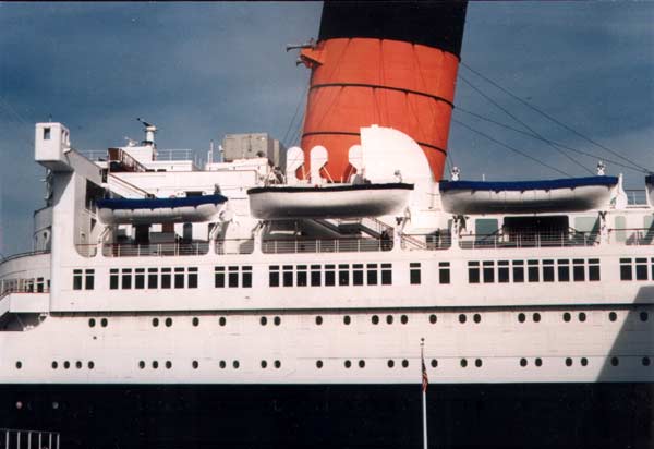
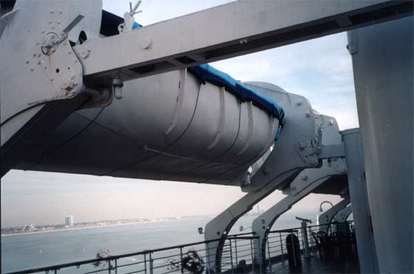
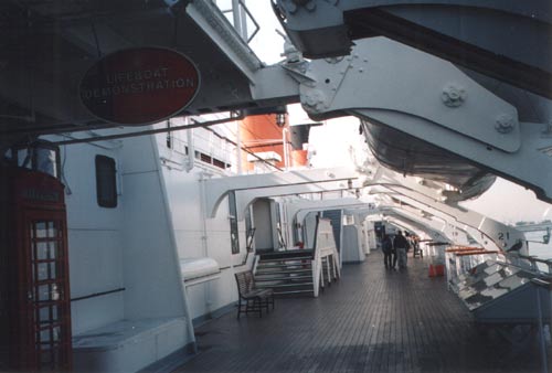
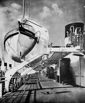
The arrangement of the davits is shown by the drawing reproduced in Fig. 2 (above), while their appearance is admirably illustrated by the photograph of the sun-deck promenade reproduced in Fig. 3. (below). The davits consist essentially of sloping trackways, down which run the cradles carrying the lifeboats. The movement is initiated and maintained by gravity, and is controlled by suitable winches.
Each trackway consists of two rolled steel channels robustly braced into a single element, the webs being outermost, and the track wheels of the carriage run on the upper flanges of these channels. The arrangement adopted gives maximum stability in all directions, including fore and aft, the cradles remaining in their correct position relative to the trackways and running perfectly thereon, even when under severe conditions of combined list and trim. The lower flanges of the trackwavs are united by welded-steel strips, in order to prevent grease. etc., from falling on to the deck below. Beyond the foot of the cradle in the stowed position, the upper flanges of the trackways are protected by tightly stretched flexible guards, which fold and fall clear automatically as the cradle moves down. These guards protect the trackwavs from the danger of ice formation, and, incidentally, enhance considerably the appearance of the davits. The arms and carriages are of fabricated construction, the arms being of rectangular box-section, assembled by electric welding and hermetically sealed. The carriages are also of welded construction, their form being largely dictated by strength considerations. The care taken in the design has resulted in a davit the strength of which is remarkable in relation to the very moderate weight involved. An additional important refinement is the keel support incorporated in each carriage. Just before the stowed position is reached in the recovery operation, the support is automatically raised to engage the keel of the boat, thereby relieving the falls, etc., of load.
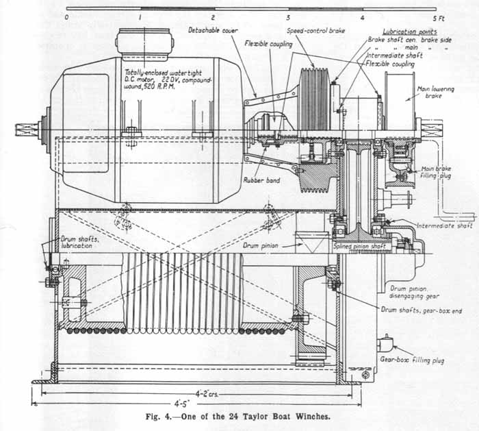
The various rope sheaves are of cast steel, and are carried by roller bearings. To facilitate the recovery of the boats, 24 electrically driven winches, also supplied by Messrs. Samuel Taylor and Sons (Brierley Hill), Ltd., are installed. These winches are of the spur-gear type, having two reductions. The primary gear is of the double-helical design, and is enclosed in an oiltight gear box. The secondary gear is open, but is housed in the winch casing. The electric motors, which have been manufactured by the British Thomson-Houston Co., Ltd., of Rugby, and which are each of 20 H.P., are of the totally-enclosed marine type, directly connected through a flexible coupling to the primary gear shaft. On this shaft are carried the main brake and the speed-controlling brake, these being completely independent of each other. The latter, which is of the centrifugal type, has been designed to limit the speed of descent of the 36-ft. boats to 6Oft. per minute. For the emergency accident boats, however, the limit of the speed is 90ft. per minute. The design and arrangement of the boat winches are indicated by the drawing given in Fig. 4 (below).
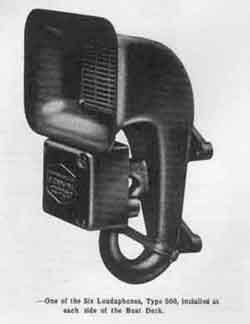
The main brakes are of the external contracting type, with metal-to-metal contacts. An interesting feature is that the brakes may remain applied during hoisting, this being achieved by means of Messrs. Taylor's silent overrunning mechanism fitted inside the brake drums. If hoisting be interrupted, the brakes come automatically into operation. It will be appreciated that the lowering of each lifeboat is effected by a single control- the main brake lever. There are no gears to engage or disengage, and the speed of lowering is automatically limited to the values already given. The winch shafts are carried on anti-friction ball bearings, which, together with accurately machine-cut gears, ensure a high overall efficiency. Each winch is provided with two drums-one for each davit of a pair. The drums may be rotated independently of each other to facilitate the adjustment of ropes, this refinement being secured by means of the sliding pinion which engages the drum gears. Individual controllers are fitted in association with the boat winches, these also being of B.T.-H. manufacture. Each comprises a dmm-type controller, resistance, circuit-breaker, isolating switch, etc., housed in a steel case. These controllers, combined with the overwinding switch on each davit, and the braking arrangements already described, reduce the hoisting operation to the simple movement of the controller handwheel. To facilitate embarkation at the sun deck, a tricing pendant, fitted between the lifeboat-lifting shackle and a suitable point on the davit carriage, automatically brings the boat into a convenient position. When the boat has received its complement, a releasing gear on the pendant is operated and the boat may then he lowered to the water. Tests have demonstrated the extreme ease with which the entire installation may be operated. The contract so successfully executed by Messrs. Samuel Taylor & Sons (Brierley Hill), Ltd., is the largest of its kind yet dealt with in this country. Loudaphones
History of Use1936-1939 – The lifeboats and other devices were in place as described above. Lifeboat drills were a routine at the beginning of every voyage. The lifeboats were never required to be put in use because of an emergency on the Queen Mary. 1940-1946 – The Queen Mary was used as a troop transport during World War II. Her carrying capacity was increased from approximately 2,000 passengers and 1,000 crew in stages to over 16,000 serviceman and crew. Six extra lifeboats were added to the ship in the aft area alongside the engineers quarters and the Verandah Grill. Two more were added in the area behind the forecastle. In addition at least 6 Carley floats (rubber rafts) were kept on the sun deck just behind the Verandah Grill and numerous life floats were carried on the upper decks. 1947-1967 – In the postwar refit (1947) all of the lifeboats added during the war were removed with the exception of a single extra lifeboat on the starboard side alongside the engineers' quarters. It was retained along with its quadrant davits.
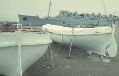
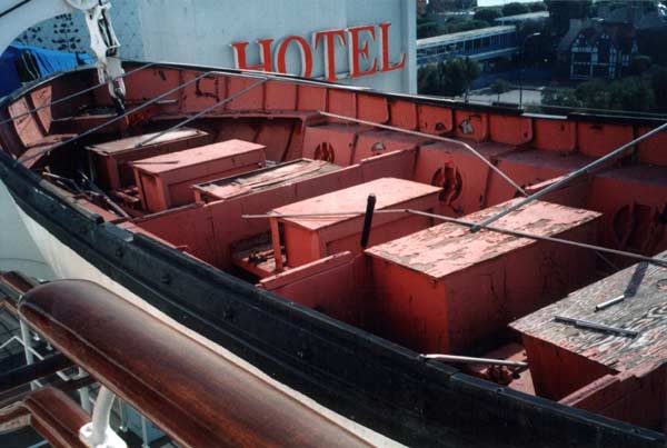
1968 to present – In the Long Beach conversion the extra boat (# 25) and davit added during the war was removed. (Traces of its davits are still seen in the plating behind position # 23.) The lifeboats were all removed from the ship and repainted at this time (see photo below).
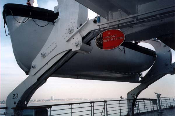
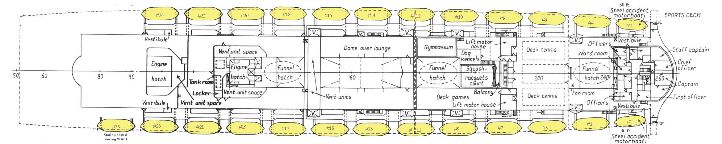
Deckplan edited by author to show today's arrangement. Since 1971 two of the 24 boats held in the original davits have been lost or destroyed. During a demonstration of the lifeboat drill for tourists, the boat in position 23 broke loose from the cables and fell to the water and was damaged or destroyed. The boat then in position # 24 was shifted in its place. It is now used for this demonstration although it is not an original Queen Mary lifeboat. In the early 1990’s while Disney operated the Queen Mary, the lifeboat in position # 22 was removed with the intent of creating a mold to replicate some or all of the 36ft. boats. This project was not complete when Disney left the Queen Mary in late 1992. The boat was left on property, but was not re-hung. The current location of this lifeboat is unknown. During the Disney era at the Queen Mary (1987-1992) the white canvas tarps in use on the lifeboats were replaced by bright blue tarps. Early photographs of the Queen Mary indicated that they were originally a buff/tan in color. Restoration Potential and PlansThe present plan is to continue with the patch and paint approach to the remaining lifeboats. There are no plans for restoration of existing or replacement of the two lost lifeboats. The photos below were taken by the author Dec 29, 2001. Click on any photo to expand it to full-size.
|
||||||||||||||||||||||||||||||||||||||||||||||||||||||||||||||||||||

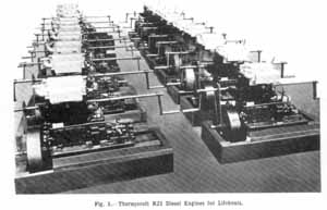 Each boat is equipped with an l8-B.H.P. two-cylinder Diesel
engine (illustrated in Fig. 1), which drives the propeller through
reduction-reversing gear incorporated in the engine. These engines have been
manufactured by Messrs. John I.Thornycroft & Co., Ltd., of Southampton and
London, and are of their RJ/2 design. The power is sufficient to give the
fully-laden 36-ft. boats a speed of 6 knots in reasonably smooth water. The
cylinder dimensions are -Diameter, 4in.; and stroke, 6in. The full power is
developed at 1,200 r.p.m., the self-contained reduction-reversing gear giving a
propeller speed both ahead and astern of 780 r.p.m. The weight of each engine
and its associated gearing is approximately 12 cwt., and the fuel consumption
per hour is about 10 pints of oil.
Each boat is equipped with an l8-B.H.P. two-cylinder Diesel
engine (illustrated in Fig. 1), which drives the propeller through
reduction-reversing gear incorporated in the engine. These engines have been
manufactured by Messrs. John I.Thornycroft & Co., Ltd., of Southampton and
London, and are of their RJ/2 design. The power is sufficient to give the
fully-laden 36-ft. boats a speed of 6 knots in reasonably smooth water. The
cylinder dimensions are -Diameter, 4in.; and stroke, 6in. The full power is
developed at 1,200 r.p.m., the self-contained reduction-reversing gear giving a
propeller speed both ahead and astern of 780 r.p.m. The weight of each engine
and its associated gearing is approximately 12 cwt., and the fuel consumption
per hour is about 10 pints of oil.
 The davit is unique in that each cradle consists of two
parts-an arm and a carriage. The arm is pivoted to the carriage so that, as the
cradle moves down the trackway, the arm swings outboard, carrying the boat with
it into the lowering position. As the carriage reaches the outboard position, it
(and the lower portion of the arm) experiences a retardation, while the speed of
the upper end of the arm is maintained. As a result when the carriage reaches
the outboard position, the impact on the gear and on the ship's structure, due
to the inertia forces involved by the destruction of momentum, is much reduced.
The davit is unique in that each cradle consists of two
parts-an arm and a carriage. The arm is pivoted to the carriage so that, as the
cradle moves down the trackway, the arm swings outboard, carrying the boat with
it into the lowering position. As the carriage reaches the outboard position, it
(and the lower portion of the arm) experiences a retardation, while the speed of
the upper end of the arm is maintained. As a result when the carriage reaches
the outboard position, the impact on the gear and on the ship's structure, due
to the inertia forces involved by the destruction of momentum, is much reduced.
 During the following 20 years in service on the North Atlantic the original
complement of lifeboats of two sizes - 30 ft and 36 ft. in length - were
routinely inspected and perhaps shifted in position on the Queen Mary. At
some point, a few lifeboats from other ships in the Cunard fleet were
swapped with those from the Queen Mary. In August of 1967 three
fiberglass-bottom lifeboats from the Sylvania were transferred to the Queen
Mary. As a result was that when the Queen Mary arrived in Long Beach on
December 9, 1967 she was carrying a mixed compliment of lifeboats – some
original equipment of the Queen Mary, others not.
During the following 20 years in service on the North Atlantic the original
complement of lifeboats of two sizes - 30 ft and 36 ft. in length - were
routinely inspected and perhaps shifted in position on the Queen Mary. At
some point, a few lifeboats from other ships in the Cunard fleet were
swapped with those from the Queen Mary. In August of 1967 three
fiberglass-bottom lifeboats from the Sylvania were transferred to the Queen
Mary. As a result was that when the Queen Mary arrived in Long Beach on
December 9, 1967 she was carrying a mixed compliment of lifeboats – some
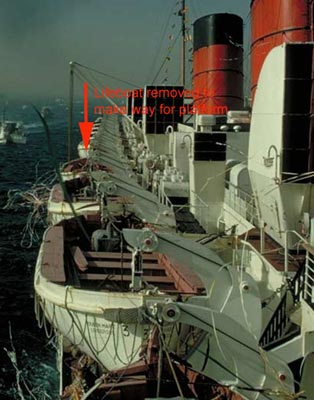
original equipment of the Queen Mary, others not.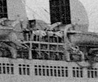 When the Queen Mary was used for cruising, the lifeboats in stations # 9
and #10 were removed and replaced with boarding platforms which were
essentially pontoons. These could be lowered and connected to stairs from
R deck. The platforms made it easier for passengers to board waiting
tenders to take them ashore. This arrangement would only be required in
ports without deep water access for the Queen Mary to dock.
When the Queen Mary was used for cruising, the lifeboats in stations # 9
and #10 were removed and replaced with boarding platforms which were
essentially pontoons. These could be lowered and connected to stairs from
R deck. The platforms made it easier for passengers to board waiting
tenders to take them ashore. This arrangement would only be required in
ports without deep water access for the Queen Mary to dock.